Gyroscopes
On a trip to the local flea market I bought about a dozen pieces of scrap brass
in the shape of right triangles with a curved hypotenuse. The guy who sold them to me said they were left over from a job where
36'' diameter circles were cut out of huge pieces of 1/2'' thick brass plate.
Each piece I bought was 14'' long and weighed five pounds. I had no idea what I
would ever use them for, but at a dollar apiece, I just couldn't pass them up.
About a year later I found a large set of brand new bimetal hole saws at the
same flea market. When I got home I decided to test them out on a piece of this
brass that was still gathering dust on my machine shop floor. I spent a few
hours cutting circular disks of various sizes and then cutting the centers out
of some of those to make large rings. It wasn't until I turned some of the rings
and disks down on the lathe so that they nested perfectly inside each other that
I started to imagine a gyroscope. The design took shape gradually as I continued
fitting the different size rings inside each other. I ended up making two of
these gyroscopes, and this project was one of my all time favorites.
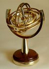
Each ring is free to rotate 360º on its axis and is held in place by two set
screws. The rotor is mounted on a 1/4'' diameter steel shaft, the ends of which
are turned to 60º points that spin in matching countersinks in adjustable bronze
screws.
The size of the gyroscope was limited by the size of the pieces of scrap brass,
thus the incomplete outer ring which is 4 3/4'' diameter.
The end of the set screws on the outer rings are turned to a 60º point which
fits in a matching countersink on the inner rings. By turning the setscrew, all
play can be adjusted out so that the rings turn freely without any vibration
while the rotor is spinning.
There is about 1/16'' clearance between each of the three rings. The adjustable
bearing that accepts the end of the rotor shaft is made from 1/4'' bonze welding
rod.
The four elongated grooves in each ring were cut on the milling machine with the
ring mounted on the rotary table. An end mill was lowered into the ring, and
then the rotary table turned to advance the cutter along the circumference. The
three large holes which form the spokes of the rotor were cut in a similar way,
but with the rotary table turned perpendicular to the spindle of the machine.
The gyroscope's rotor is made to spin by threading a string trough the hole in
the rotor's shaft, winding it up, and giving the string a firm pull. While the
rotor is spinning, if the gyroscope is lifted by its base and turned upside down
or to any other position, the rings of the gimbals rotate around each other
allowing the rotor to always maintain a constant position in relation to the
earth. This principle enables more sophisticated gyroscopes to guide airplanes
and rockets. Space stations use gyroscopes to maintain their orientation to the
sun. Huge gyroscopes weighing many tons are used in ships to enable them to
resist being buffeted by the ocean waves. As every kid who grew up in the 50's
and 60's knows, gyroscopes are really cool!
Click image below to view photo gallery

